Food Plant Steam System Sizing: Engineering Calculations for Process and CIP Applications
[trp_language language=”en_US”]
Steam System Design for Food Plants in the United States
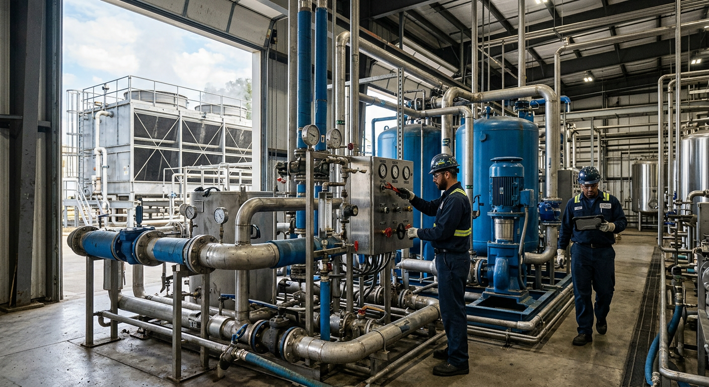
Steam remains one of the most important utilities in American food and beverage manufacturing. It heats kettles, retorts, blanchers, pasteurizers, jacketed tanks, CIP skids, hot water sets, washdown systems, and building support loads. In facilities from dairy plants in Wisconsin to protein processors in Arkansas, beverage co-packers in Texas, and sauce plants near the Port of Savannah, accurate steam sizing directly affects production uptime, sanitation performance, energy cost, and future expansion.
Quick Answer

The fastest way to size a food plant steam system is to calculate the peak simultaneous steam load for process equipment, CIP, sanitation, domestic support, and distribution losses, then apply a practical design margin based on startup events and future capacity. In most U.S. food plants, undersized systems fail during overlapping events such as morning startup, retort heat-up, multiple kettle calls, and CIP return-to-temperature cycles. Oversized systems, on the other hand, create poor turndown, short boiler cycling, unstable pressure, and unnecessary fuel spend.
A sound engineering approach usually includes these steps:
- List every steam user and define pressure, duty cycle, and batch overlap.
- Convert each process duty to pounds per hour of steam using heat balance calculations.
- Identify coincident peak demand rather than simply summing nameplate loads.
- Size boilers for maximum realistic demand plus reserve strategy, not guesswork.
- Design distribution headers for acceptable velocity and pressure drop.
- Recover condensate wherever return quality, layout, and contamination risk allow.
- Separate culinary or clean steam requirements from plant utility steam.
- Include pressure reducing stations, steam traps, controls, and monitoring from the start.
For many United States projects, the most economical solution is not the largest boiler. It is the best-matched system architecture: one or more boilers with proper turndown, a distribution network laid out for dry steam, high condensate return, and controls aligned with actual operating sequences. This matters especially in fast-growth regions such as North Carolina, California’s Central Valley, greater Chicago, and the Dallas-Fort Worth manufacturing corridor, where plants often expand in phases and utility capacity decisions made early can lock in operating cost for years.
| Plant Area | Typical Steam Use | Pressure Range | Load Pattern | Main Sizing Risk | Design Note |
|---|---|---|---|---|---|
| CIP system | Tank heating, solution recovery, hot rinse | 15-60 psig | Cyclic | Ignoring reheat peaks | Model batch overlap and hold temperatures |
| Retort | Come-up, hold, venting support | 50-120 psig | High peak | Using average instead of startup load | Size for worst-case heat-up event |
| Jacketed kettle | Cooking, simmering, sauce prep | 15-80 psig | Batch | Assuming constant demand | Use product-specific heat balance |
| Pasteurizer/HTST support | Hot water generation | 30-100 psig | Stable | Missing control valve authority | Review dynamic response |
| Sanitation/washdown | Hot water generation | 15-60 psig | Shift-based | Leaving out shift change overlap | Include sanitation schedule |
| Building support | Humidification, freeze protection, HVAC | 5-30 psig | Seasonal | Ignoring winter conditions | Include climate-specific loads |
The table above shows why steam sizing must reflect actual operating behavior. Average load rarely predicts the real peak that determines boiler and header capacity.
Methods for Calculating Steam Demand

Steam demand calculation starts with a thermal inventory. Every user is listed with operating pressure, target temperature, product mass, heating time, jacket efficiency, startup frequency, and simultaneous use. In food applications, process steam load generally falls into two categories: direct equipment heating and indirect hot water generation for CIP or process loops.
The core formula is a heat balance:
Required heat = mass x specific heat x temperature rise, plus vessel losses, plus heat-up of metal surfaces, plus safety allowances appropriate to the process.
That heat duty is then converted into steam flow using the usable latent heat at the selected steam pressure. For example, if a sauce kettle in Ohio must raise 2,000 pounds of product from 70°F to 190°F in 30 minutes, the engineer calculates the product heat load, adds vessel and piping losses, and divides by the available Btu per pound of condensing steam. That yields a realistic pounds-per-hour steam requirement. The same logic applies to cheese vats in Wisconsin, protein cookers in Nebraska, and aseptic support skids in New Jersey.
Three methods are common in practice:
- Bottom-up equipment calculation: best for new plants and major expansions.
- Historical trend analysis: useful for brownfield sites with reliable metering.
- Hybrid method: combines thermal calculations with utility data for validation.
For CIP systems, demand is often underestimated because engineers only count tank heating and forget recovery losses, make-up water swings, and concurrent circuits. A multi-tank CIP skid serving fillers, tanks, and lines in a beverage facility near Los Angeles may have a relatively modest average steam draw but a very high short-duration peak when fresh caustic, acid, and hot rinse cycles are staged poorly. Sequencing can reduce installed boiler capacity as effectively as hardware changes.
| Load Type | Calculation Basis | Best For | Primary Inputs | Common Error | Recommended Check |
|---|---|---|---|---|---|
| Product heating | Mass and temperature rise | Kettles, tanks, cookers | Batch size, specific heat, cycle time | Ignoring metal heat-up | Field verify heat-up time |
| Water heating | Flow and temperature rise | CIP, washdown, hot water sets | GPM, inlet temp, outlet temp | Using annual average water temp | Use winter cold-water design |
| Heat exchanger duty | UA or energy balance | HTST, process loops | Approach temp, flow, fouling factor | Missing fouling allowance | Review clean and dirty cases |
| Retort startup | Transient peak analysis | Retort, sterilization | Chamber volume, venting, schedule | Using hold load only | Model come-up and recovery |
| Building support | Envelope and seasonal duty | HVAC, freeze protection | Climate, infiltration, occupancy | Leaving out winter operations | Use local weather data |
| Distribution loss | Pipe surface and fitting loss | Campus and long runs | Length, insulation, ambient temp | Assuming zero line loss | Include startup warm-up loss |
The table above shows why a single rule-of-thumb value is rarely enough. Accurate sizing depends on process detail.
Where plants already operate, trend data can sharpen the model. Boiler fuel consumption, feedwater make-up, condensate return rate, and header pressure trends reveal actual demand shape by shift and season. Facilities in the Midwest often show winter spikes due to lower incoming water temperature and space-conditioning loads. Gulf Coast plants may show higher summer swings associated with sanitation schedules and beverage throughput.
The line chart illustrates a realistic modernization trend for steam utility investment in the United States as plants pursue efficiency, electrification readiness, and tighter sanitation control through 2026 and beyond.
Criteria for Boiler Sizing and Selection

Boiler sizing should reflect peak coincident steam demand, required redundancy, turndown, feedwater quality, emissions constraints, and growth plans. In food processing, boiler selection is as much about operations strategy as thermal capacity. A single large firetube boiler may look cheaper on day one, but two smaller units can improve turndown, maintenance flexibility, and resiliency during production surges.
Selection criteria usually include:
- Peak load in pounds per hour.
- Minimum stable load and turndown ratio.
- Steam pressure required at the highest-pressure user.
- Feedwater temperature and deaeration strategy.
- Fuel availability: natural gas, dual fuel, propane backup, or fuel oil in special cases.
- Emissions permitting, especially in California and dense air districts.
- Redundancy philosophy such as N, N+1, or limited emergency production.
- Expansion path for future lines, shifts, or packaging formats.
For example, a beverage plant near Charlotte planning to scale from one line to three may benefit from modular capacity rather than a single installed maximum. Likewise, a protein facility in Kansas City with sanitation-critical morning startups may prioritize fast response and strong low-load stability.
| Boiler Option | Best Fit | Advantages | Limitations | Typical Food Use Case | Planning Comment |
|---|---|---|---|---|---|
| Single firetube boiler | Stable medium loads | Simple, proven, lower first cost | Less redundancy | Small sauce or dairy plant | Works if downtime risk is acceptable |
| Two firetube boilers | Variable batch loads | Better turndown and backup | Higher installed cost | Regional co-packer | Common U.S. growth strategy |
| Watertube boiler | High pressure or large demand | Fast response, high capacity | More complex water quality demands | Large retort or campus utility plant | Best where rapid changes occur |
| Electric boiler | Selective clean utility duty | Low point-of-use emissions | Power cost and grid limits | Pilot plant or clean steam support | Useful in decarbonization plans |
| Modular packaged boilers | Phased expansion | Scalable, easier staging | Need thoughtful controls integration | New beverage or RTD plant | Supports startup to scale transition |
| Dual-fuel system | Energy resilience | Fuel flexibility | More permitting and storage needs | Critical operations near ports or storm zones | Useful on Gulf and East Coast sites |
The table above compares common boiler strategies. The right choice depends on production pattern, resilience needs, and long-term capital planning rather than equipment price alone.
By 2026, boiler rooms in the United States are increasingly shaped by three trends: digital monitoring, stricter sustainability expectations, and resilience planning. Plants are installing better blowdown heat recovery, O2 trim, combustion tuning, remote alarms, and integration with energy dashboards. Some projects also evaluate hybrid strategies where traditional gas-fired steam remains essential for core thermal loads, while electric hot water systems handle ancillary duties.
Designing the Steam Distribution Network
Once the boiler plant is sized correctly, the steam distribution network must deliver dry steam at stable pressure to each point of use. Poor network design can waste the benefit of an otherwise well-chosen boiler. In many brownfield plants from New Jersey to California, the real issue is not generation capacity but distribution losses, pressure instability, water hammer, and lack of drainage at low points.
Good distribution design includes proper header sizing, branch takeoff orientation, pitch for condensate drainage, expansion allowance, insulation, drip legs, separators where needed, and practical routing around production areas. Long runs to remote packaging halls or warehouse utility drops, such as those found in large Texas or Georgia sites, require special attention to line loss and condensate formation.
Target steam velocity varies by system, but the principle is straightforward: keep velocities reasonable, avoid excessive pressure drop, and protect steam quality. Undersized headers increase velocity and entrainment. Oversized pipes can increase cost and warm-up time. The network should be designed around the actual pressure tiers in the plant, often with a main high-pressure header from the boiler room and localized reduction for users such as kettles, hot water sets, and jacketed tanks.
| Network Element | Function | Key Design Check | Common Failure Mode | Operational Impact | Recommended Action |
|---|---|---|---|---|---|
| Main header | Bulk steam transport | Pressure drop and velocity | Undersized piping | Low end-of-line pressure | Recalculate for peak coincident load |
| Branch takeoff | Supplies equipment area | Takeoff from top of header | Wet steam carryover | Poor heat transfer | Use top takeoffs and drip legs |
| Drip leg | Removes condensate | Spacing at low points and intervals | Omitted or too small | Water hammer | Add traps and proper pocket sizing |
| Insulation | Reduces heat loss | Thickness by temperature | Damaged cladding | Energy waste and safety risk | Audit annually |
| Expansion allowance | Handles thermal growth | Loops, guides, anchors | Rigid routing | Stress and leaks | Review mechanical support layout |
| Pressure zoning | Matches user needs | Tiered pressure strategy | Single pressure everywhere | Control instability | Segment with PRV stations |
The table above highlights the physical details that separate stable steam systems from troublesome ones.
The bar chart compares realistic relative steam demand intensity across major food and beverage segments in the U.S. market. Retort, protein, and prepared foods typically create the most aggressive steam peaks.
In large metropolitan and port-connected zones such as Houston, Long Beach, Philadelphia, and Savannah, facility layouts may be constrained by older buildings or aggressive construction schedules. In these cases, pipe routing must be coordinated tightly with structural, plumbing, electrical, and controls work to avoid costly field changes. This is where integrated utility design offers real value.
Manufacturers evaluating network upgrades can learn more about integrated process and utility delivery through food and beverage engineering services that align process goals with utility infrastructure instead of treating steam as a standalone package.
Condensate Recovery System Design
Condensate recovery is one of the fastest-return improvements in food plant steam systems. Hot condensate contains both thermal energy and treated water value. Returning it reduces boiler fuel demand, make-up water consumption, chemical use, and blowdown rates. In many U.S. plants, raising condensate return from 45 percent to 75 percent can materially improve annual operating cost, especially where water, sewer, and gas rates are rising.
Not every condensate stream should be returned. The decision depends on contamination risk, flash steam behavior, pressure differential, lift requirements, and product contact concerns. For example, condensate from utility steam jackets in a sauce plant is often suitable for return if the system is maintained well. Condensate from direct-contact or suspect heat exchange applications may need segregation.
Key design choices include gravity return versus pumped return, vented receiver sizing, flash steam handling, NPSH for pumps, and location of polishers or monitoring points. A plant near Denver may face different return temperature and altitude considerations than one in coastal Louisiana. Brownfield sites with long underground runs may also need corrosion review and insulation upgrades before increasing return rates.
| Condensate Decision Point | Why It Matters | Preferred Practice | Risk if Ignored | Typical U.S. Scenario | Engineer Review Item |
|---|---|---|---|---|---|
| Return percentage target | Controls energy savings | Set measurable KPI | Missed savings | Multi-line food plant | Benchmark current return rate |
| Contamination control | Protects boiler water | Segregate suspect streams | Boiler water upset | Flavor, dairy, or aseptic plant | Add conductivity or TOC checks |
| Pump sizing | Ensures reliable return | Account for flash and elevation | Cavitation and overflow | Campus-style facility | Review NPSH and venting |
| Receiver volume | Buffers variable flow | Match cycle behavior | Short cycling | Batch operation | Model surge conditions |
| Insulation and heat retention | Preserves energy | Insulate return piping | Lost temperature value | Outdoor lines in Midwest | Inspect exposed routes |
| Monitoring and metering | Supports continuous improvement | Trend return temp and flow | Hidden performance decline | Enterprise utility program | Integrate with SCADA |
The table above explains where condensate systems often gain or lose value. A recovery program succeeds when it is designed as a quality-controlled utility loop, not just a drain return.
The area chart shows a realistic shift toward higher condensate recovery as sustainability and utility-cost management gain importance through 2026.
Clean Steam for Direct Product Contact
Utility steam and clean steam are not interchangeable. When steam has any chance of direct or indirect product contact under a plant’s quality framework, the design basis must be defined carefully with QA, operations, and engineering. In pharmaceutical-style or high-care food environments, clean steam may be required for humidification in controlled zones, sterilization support, or direct-contact functions where boiler chemical carryover cannot be accepted.
Clean steam systems typically require purified feedwater, compatible materials such as stainless steel, sanitary design principles, and controlled generation equipment. The exact requirement depends on product category, regulatory interpretation, and customer standards. A dairy ingredients plant shipping to demanding consumer brands may set stricter steam quality expectations than a conventional prepared foods site, even when both are within the same state.
In food processing, the first question should be functional necessity: does the application truly require clean steam, culinary steam, or simply well-managed utility steam through a barrier heat exchanger? Over-specification adds cost. Under-specification adds risk. This decision matters in aseptic filling projects, retort support, ingredient injection systems, and high-care packaging areas.
Plants developing direct-contact or hygienic steam applications often pair clean utility strategy with broader sanitary equipment planning. For manufacturers considering new skids, tanks, or integrated processing assets, custom process manufacturing and equipment solutions can help align utility design with hygienic standards from the beginning.
Pressure Reducing Station Design
Most food plants generate steam at one pressure and use it at several lower pressures. Pressure reducing stations provide controlled step-down while protecting steam quality, downstream equipment, and operator safety. A good PRV station includes more than a single reducing valve. It needs proper isolation, straining, drip removal, pressure sensing, safety relief, bypass strategy where justified, and enough straight run for stable control.
Common station mistakes include undersized valves for startup load, oversized valves that hunt at low flow, poor trap drainage upstream, no separator where wet steam is likely, and relief devices that do not match actual downstream pressure class. These issues often show up in real facilities as unstable jacket temperatures, erratic control valves, and nuisance trips on hot water sets.
In plants with multiple pressure levels, it is often smart to reduce pressure close to the user group rather than once centrally for the whole plant. Local reduction can improve control and reduce unnecessary high-velocity low-pressure piping. For example, a large beverage campus in Phoenix may use a medium-pressure distribution loop with dedicated low-pressure stations for syrup prep, bottle washer support, and sanitation hot water generation.
| PRV Station Component | Purpose | Design Priority | Typical Failure | Result in Plant | Best Practice |
|---|---|---|---|---|---|
| Isolation valves | Maintenance access | Safe shutdown | Limited serviceability | Longer downtime | Provide upstream and downstream isolation |
| Strainer | Protects valve internals | Debris removal | Plugging or omission | Poor control response | Blowdown and clean routinely |
| Drip trap set | Removes upstream condensate | Dry steam to valve | No drainage | Water hammer and erosion | Install before reduction point |
| PRV body and trim | Pressure control | Turndown and Cv match | Oversized valve | Hunting and instability | Select by min and max flow |
| Relief valve | Downstream overpressure protection | Code compliance | Wrong setpoint | Safety risk | Coordinate with downstream MAWP |
| Bypass arrangement | Operational flexibility | Only where justified | Uncontrolled manual use | Pressure upsets | Lock and procedure-control bypass use |
The table above explains why PRV stations should be treated as engineered assemblies rather than accessories.
Steam Trap Selection and Upkeep
Steam traps are small devices with large consequences. Incorrect selection or poor maintenance leads to live steam loss, flooded heat exchangers, water hammer, slow batch times, and degraded sanitation performance. Every food plant should treat steam trap management as part of its utility reliability program, not as a minor maintenance task.
Trap choice depends on application. Float and thermostatic traps often fit modulating heat exchangers and unit heaters. Inverted bucket traps may serve drip applications. Thermodynamic traps may suit certain high-pressure drip services. Thermostatic air vents and startup venting behavior also matter, especially where rapid heat-up is required.
A trap survey should classify location, service type, pressure, condensate load, failure mode, and criticality. In many plants, 10 to 20 percent of installed traps are underperforming at any given time. That can quietly erase fuel savings from a new boiler project. Large sites in Illinois, Pennsylvania, and California often find six-figure annual losses once failed-open traps and bypass leakage are quantified.
Maintenance best practices include annual or semiannual survey routes, ultrasonic and thermal inspection, trap tagging, replacement standards, and integration into CMMS systems. If a facility lacks a current map of steam traps, it lacks control of one of its simplest utility efficiency levers.
The comparison chart shows why many growing food plants favor modular utility strategies even when the single-boiler option appears cheaper at first glance.
Manufacturers seeking a practical example of utility optimization tied to broader plant performance can review project case studies that show how engineering decisions affect throughput, capital efficiency, and operating results.
About Disruptive Process Solutions
Disruptive Process Solutions supports food and beverage manufacturers across the United States and Canada with a design-build-manage approach that connects process engineering to real capital outcomes. Rather than treating steam, CIP, controls, and installation as disconnected scopes, the company works across utility and process systems so owners can make faster, better-informed project decisions.
From a technological capabilities standpoint, DPS brings integrated engineering across process, mechanical, plumbing, electrical, structural, and controls disciplines. That matters when a steam system must coordinate with PLC logic, SCADA visibility, batching, recipe control, energy monitoring, and production sequencing. In a modern plant, correct steam sizing is not just a boiler-room exercise; it is part of a wider operating model.
From a manufacturing capabilities standpoint, DPS also supports custom process equipment that can be aligned with utility needs from day one. That includes tanks, CIP systems, cooking vessels, and related processing assets that benefit from a coordinated approach to steam pressure, condensate routing, sanitary design, and automation. This is especially valuable in projects where utility assumptions can easily drift away from actual equipment performance.
From a service capabilities standpoint, DPS works across capital planning, feasibility, owner’s representation, detailed engineering, general contracting functions, installation management, commissioning, and system integration. For manufacturers expanding in high-growth U.S. regions such as North Carolina, Texas, California, and the Midwest, that end-to-end delivery model can reduce handoff errors and improve schedule control.
Companies that want to understand the team and delivery philosophy in more detail can visit about Disruptive Process Solutions. The focus is straightforward: profitable projects, transparent advice, and utility and process decisions that hold up in the field.
Frequently Asked Questions
How much design margin should be added to a food plant steam load?
There is no universal percentage that fits every plant. Margin should reflect uncertainty, startup behavior, and future growth. A well-defined project may only need a modest margin, while a phased expansion with unknown line additions may justify more. Blindly adding 30 percent without reviewing coincidence often causes oversizing.
Should CIP be sized on average or peak demand?
Peak coincident demand. CIP systems are highly cyclical, and the highest steam draw often occurs when heating fresh solutions or recovering tank temperatures between circuits. Sequencing changes can reduce peak demand significantly.
When is clean steam necessary in food manufacturing?
When the application, customer requirement, or regulatory interpretation demands steam quality beyond normal utility steam, especially for direct product contact or highly hygienic support functions. The answer depends on the exact application, risk assessment, and quality standard.
Is condensate always worth returning?
Usually yes, but not always. Return suitability depends on contamination risk, elevation, flash behavior, pumping needs, and economics. Segregation is often the right answer where some streams are clean and others are questionable.
What is the most common steam distribution mistake?
Ignoring condensate drainage and pressure drop. Many plant issues blamed on boiler size actually come from wet steam, poor trapping, inadequate header design, or badly placed pressure reduction.
How often should steam traps be inspected?
Critical plants often inspect annually or semiannually depending on service severity. A trap program should be data-driven and tied to maintenance planning, not handled only after failures become obvious.
Can one boiler support both process steam and future expansion?
Sometimes, but only if capacity, turndown, and outage risk are acceptable. Many growing U.S. facilities choose modular or staged boiler capacity to protect expansion flexibility and maintenance uptime.
How do 2026 sustainability trends affect steam system design?
They are pushing plants toward higher condensate recovery, better metering, lower emissions burners, heat recovery, digital monitoring, and utility strategies that can adapt to changing fuel, electricity, and water economics. Corporate ESG commitments are also increasing scrutiny of boiler efficiency and water reuse.
What information should be ready before starting a steam sizing study?
Equipment list, process temperatures, batch sizes, cycle times, required pressures, sanitation schedule, line expansion plans, available fuel, water quality data, plant layout, and any utility trend history. The better the inputs, the more reliable the sizing outcome.
In summary, food plant steam system design in the United States should be built on realistic process calculations, practical utility architecture, and clear understanding of how the plant will operate at peak. That means sizing for simultaneous demand, selecting boilers for both efficiency and resilience, delivering dry steam through a disciplined network, recovering condensate wherever sensible, and separating clean steam requirements from ordinary utility service. Plants that take this approach are better positioned for capacity growth, energy control, and reliable sanitation performance in 2026 and beyond.
[/trp_language]
Complete Company Portfolio
About the Author: Disruptive Process Solutions (DPS)
The DPS team combines process engineering expertise with real-world food and beverage manufacturing experience. Our content focuses on process optimization, production efficiency, facility improvements, and practical solutions that help manufacturers operate more effectively in a rapidly evolving industry.
Share