Aseptic Beverage Plant Design
[trp_language language=”en_US”]
Aseptic Beverage Facility Design for the United States Market
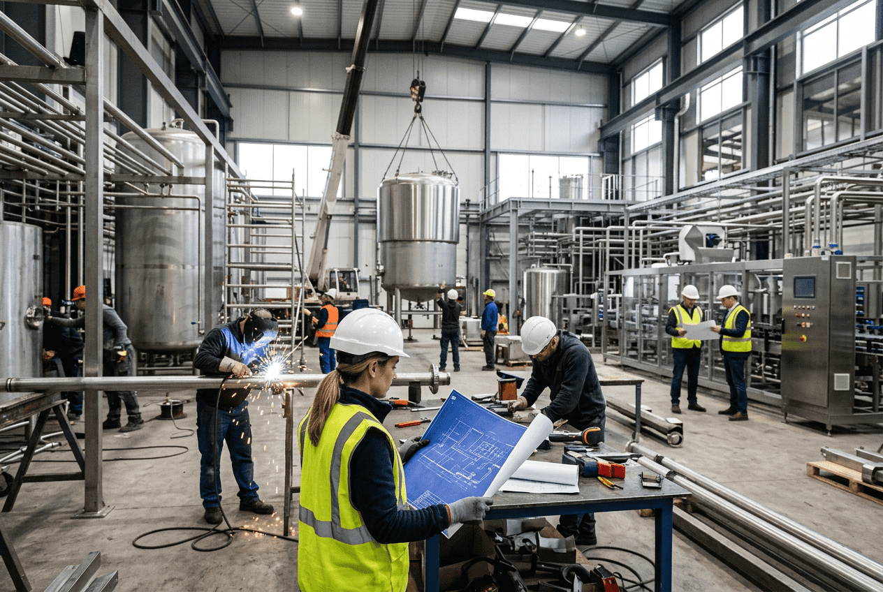
Aseptic beverage plant design in the United States requires more than placing a sterilizer next to a filler. A successful facility must integrate hygienic zoning, validated air handling, sterile product pathways, barrier systems, utility redundancy, compliant materials, and practical maintenance access. For beverage manufacturers producing shelf-stable dairy drinks, protein beverages, low-acid teas, nutritional products, juices, functional beverages, and ready-to-drink formulations, the plant layout directly affects contamination risk, throughput, labor efficiency, and return on capital.
In major U.S. production corridors such as Chicago, Dallas-Fort Worth, Atlanta, the Inland Empire, Central Valley California, and the Carolinas, aseptic projects are increasingly driven by co-packing demand, freight optimization, and the need to serve national retail networks through hubs near ports like Savannah, Los Angeles/Long Beach, Houston, and New York/New Jersey. That makes facility design a business decision as much as an engineering one. The right design lowers startup risk, shortens commissioning, and improves first-year profitability.
For owners evaluating a greenfield build, a brownfield retrofit, or an aseptic line expansion, it is critical to align processing technology, room classification, packaging format, utility capacity, sanitation strategy, and regulatory expectations from the beginning. Companies seeking a partner that can connect engineering with execution often turn to firms with process, utilities, controls, and installation capability under one roof. Disruptive Process Solutions is one example of a U.S.-focused engineering partner that approaches these projects from both manufacturing performance and capital efficiency perspectives.
Quick Answer

An aseptic beverage plant should be designed around a one-way flow of product, packaging, personnel, waste, and air. The highest-risk zone is the filling and closure area, which typically requires a Grade A critical environment protected by localized unidirectional airflow and separated from surrounding support zones by barriers or isolators. Upstream sterilization, validated CIP/SIP, filtered utilities, and tightly controlled HVAC are essential. In the United States, the design must also support FDA process requirements, sanitary equipment selection, cleanability, and documented environmental control.
For most projects, the best results come from planning six items together: process flow, hygienic zoning, sterile boundary control, utility loads, automation strategy, and future expansion. Aseptic beverage producers commonly compare wet sterilization systems such as hydrogen peroxide and steam-assisted methods with dry approaches for packaging decontamination, depending on container type, speed, product sensitivity, and line economics. Capital cost is significant, but the payoff can be attractive when the plant is designed for high uptime, broad SKU flexibility, and scalable output.
| Priority | Why It Matters | Design Focus |
|---|---|---|
| Sterile product protection | Prevents post-process contamination | Closed product path, sterile valves, SIP validation |
| Critical zone air control | Protects open containers during filling | Grade A airflow, HEPA filtration, pressure cascade |
| Personnel and material segregation | Reduces cross-contamination | Separate gowning, pass-throughs, dedicated entries |
| Utility reliability | Prevents sterile boundary loss | Redundant steam, air, chilled water, controls |
| Sanitary equipment selection | Improves cleanability and compliance | 3-A aligned components, drainability, hygienic welds |
| Scalability | Supports future line additions | Reserved space, oversized headers, modular controls |
The table above summarizes the design fundamentals. In practice, each item must be engineered as part of a single operating system, not treated as isolated equipment packages.
Aseptic Plant Layout Principles: Cleanroom Zones and Personnel Flow

Plant layout is the first and most important contamination control decision. A well-designed aseptic beverage facility uses progressive hygienic zoning so that people, ingredients, packaging, tools, and waste move from lower-risk to higher-risk spaces only under controlled conditions. In many U.S. projects, especially retrofits in existing beverage buildings, the biggest problem is not the filler itself but the accidental mixing of warehouse traffic, maintenance access, raw ingredient handling, and sterile packaging operations.
A practical layout typically includes raw material receiving, ingredient staging, blending, thermal treatment, aseptic surge or buffer capacity, packaging sterilization, filling, secondary packaging, palletizing, and finished goods staging. These functions should be physically arranged to avoid backtracking. Personnel flow must be separated from forklift flow whenever possible, and gowning should be staged by room classification. Maintenance access should allow technicians to service motors, drives, and panels without entering the critical sterile zone.
One-way flow works best when supported by airlocks, material pass-through chambers, and clearly defined transition points. Facilities in dense industrial markets such as New Jersey, Southern California, and greater Houston often have limited building footprints, so vertical mezzanines and utility interstitial spaces can help keep sterile production floors uncluttered. In greenfield projects, it is often worth allocating extra square footage to corridors and support rooms because cramped layouts become expensive once validation begins.
| Zone | Typical Activities | Access Level | Air Strategy |
|---|---|---|---|
| Uncontrolled support | Receiving, warehousing, non-product maintenance | General staff | Comfort HVAC |
| Controlled processing | Blending, ingredient prep, CIP support | Sanitation-trained staff | Filtered air, positive pressure |
| High hygiene | Post-UHT sterile transfer support areas | Restricted entry | Higher filtration, pressure cascade |
| Critical fill support | Package decontamination interface, bowl support | Gowned operators | Tightly controlled HVAC |
| Grade A critical point | Open container exposure, filling, closure | Minimal direct access | Unidirectional HEPA airflow |
| Post-fill protected egress | Discharge to downstream packaging | Restricted traffic | Clean transition air |
The zoning model above helps operators decide how walls, gowning rooms, and pressure relationships should be arranged. It also supports audit readiness by making hygienic intent visible in the building itself.
When layout is developed correctly, it also strengthens labor efficiency. Operators do not waste time crossing forklift lanes or moving tools through multiple sanitation barriers. Supervisors can observe critical operations from external windows or controlled corridors. This becomes increasingly valuable for high-volume co-packers serving multiple national brands from regions like Tennessee, Texas, and North Carolina, where fast changeovers and strict schedule discipline matter.
The growth trend shown above reflects why layout decisions made today should anticipate 2026 and beyond. Expansion corridors, spare clean utility capacity, and scalable automation architecture are increasingly important in the United States market.
Grade A Environment Requirements for Aseptic Filling Operations

The critical exposure point in aseptic filling is where a sterilized package, sterile product, and closure system come together. This area must be protected as a Grade A environment with localized unidirectional airflow and extremely tight operational discipline. Even when the broader room uses another controlled classification strategy, the direct filling zone is the area where contamination risk is most acute and where design details such as air velocity, turbulence control, glove interventions, and equipment access become decisive.
For beverage manufacturers, the Grade A concept is often implemented inside a protected chamber, restricted access barrier system, or isolator rather than across a large open room. This is usually more practical, easier to validate, and less expensive to maintain. The objective is to minimize human interaction with exposed sterile product contact surfaces and open containers. Equipment should be arranged so common interventions can be done from outside the critical envelope or through sanitized glove ports.
Surface finishes, slope, drainability, elimination of ledges, and reduction of particle-shedding components are all essential. So are routine environmental monitoring plans, alarm management, access control, gowning procedures, and documented line clearance. Critical zones should be designed for repeatable decontamination and for rapid restart after planned stoppages.
| Requirement | Design Response | Operational Benefit |
|---|---|---|
| Unidirectional airflow | HEPA-filtered laminar pattern over fill point | Particle and microbe control |
| Minimal intervention | External adjustments and automated change parts | Lower contamination risk |
| Sanitizable enclosure | Smooth surfaces, sealed panels, CIP/SIP-compatible design | Faster, repeatable sanitation |
| Sterile package entry | Validated decontamination tunnel or chamber | Maintains sterile boundary |
| Closure control | Sterile cap handling and protected transfer | Reduces end-of-line contamination |
| Environmental monitoring | Defined sampling points and event logging | Supports release and investigation |
This checklist is useful during design reviews, FATs, SATs, and startup planning. It also helps owners compare competing filler platforms on more than speed alone.
HVAC and Laminar Airflow System Design for Aseptic Beverage Plants
HVAC in an aseptic beverage plant is not a comfort system with better filters. It is a process-critical contamination control utility. The system must maintain directional airflow, room pressure differentials, temperature stability, humidity control, filter integrity, and recovery after door openings or short interventions. Poor HVAC design can undermine an otherwise excellent sterilization process.
For U.S. beverage facilities, especially in climates ranging from humid Florida and the Gulf Coast to dry inland California and cold Upper Midwest regions, ambient conditions heavily influence HVAC sizing and condensation management. Designers must prevent condensation near sterile areas, maintain cleanroom differentials during production peaks, and account for heat generated by UHT skids, compressors, motors, and packaging equipment. Air handling should be zoned so that the most critical spaces are not destabilized by load swings in adjacent rooms.
Laminar or unidirectional airflow should be supplied at the exposed fill zone, with return paths designed to avoid dead pockets and turbulence. Pressure cascade should generally move from cleaner to less clean areas. Door interlocks, airlocks, and properly placed return grilles are small details that have large effects. In many projects, the best performing design uses dedicated AHUs for critical zones rather than tying them into broader plant HVAC.
DPS supports projects like this by integrating structural, mechanical, plumbing, electrical, process, and controls engineering so that HVAC performance is coordinated with room layout, utility routing, and automation alarms rather than being designed in isolation. More on these integrated capabilities can be found across the company’s engineering and project services.
The bar chart highlights which categories are driving HVAC-intensive aseptic investment. Nutritional drinks, protein beverages, and dairy alternatives typically require robust sterile processing support and tight control of the fill environment.
Equipment Selection: Wet vs Dry Sterilization Technologies
Selecting sterilization technology is one of the most consequential decisions in plant design. Wet and dry systems both have roles in aseptic beverage packaging, and the right answer depends on container format, line speed, product acidity, package geometry, environmental goals, and operating philosophy. There is no universal winner.
Wet sterilization methods commonly use hydrogen peroxide, heat, steam, hot water, or combinations of these techniques. They can be highly effective and are widely proven, particularly for certain bottle, cap, and carton applications. However, they may require additional chemical handling, drying steps, residue management, and validation of concentration, temperature, and contact time.
Dry sterilization methods, often associated with certain advanced package decontamination platforms, can reduce water use and simplify some environmental burdens. They may also support cleaner machine design and lower downstream moisture concerns. On the other hand, the capital cost can be higher, and not every package type or speed target is equally suited to every dry technology.
| Factor | Wet Sterilization | Dry Sterilization | Best Fit Considerations |
|---|---|---|---|
| Water use | Higher | Lower | Sustainability targets, wastewater load |
| Chemical handling | Often more involved | May be lower depending on method | Safety procedures, storage space |
| Package compatibility | Broad for many established formats | Technology dependent | Bottle, cap, carton, pouch design |
| Line speed flexibility | Strong in proven platforms | Can be excellent in optimized systems | SKU mix and uptime goals |
| Residue and drying | Needs careful management | Often simpler | Product sensitivity and package integrity |
| Capital and validation impact | Moderate to high | Moderate to high | Total lifecycle cost, not just purchase price |
The table above shows why owners should compare total operating cost, not just machine price. Energy, water, consumables, downtime, validation burden, and operator skill requirements all affect long-term value.
From a manufacturing capability standpoint, DPS works across pasteurization and sterilization technologies including HTST, UHT, retort, flash pasteurization, and aseptic systems, while also supporting integration of tanks, CIP systems, blending, utilities, and controls. Companies exploring equipment paths can review related capabilities and proprietary systems through the process equipment portfolio.
Barrier Systems and Isolator Design for Contamination Control
Barrier systems and isolators are now central to modern aseptic beverage filling. Their purpose is simple: reduce the chance that people, surrounding air, or uncontrolled interventions compromise the critical zone. In practice, they also improve line consistency, environmental stability, and audit confidence.
A restricted access barrier system can be the right choice when the line requires some operator interaction but still needs strong separation from the surrounding room. An isolator may be more appropriate when the owner wants a more fully enclosed environment with even tighter control and reduced dependency on room classification. The decision depends on intervention frequency, line speed, package format, cleaning method, spare parts philosophy, and workforce capability.
Important design details include glove and half-suit ergonomics, visibility, sanitation access, transfer ports, pass-through sterilization, decontamination cycle time, and fail-safe responses during power or utility interruptions. The barrier is only effective if the machine remains maintainable. If operators must frequently breach the enclosure to clear jams or adjust components, the design is incomplete.
In several U.S. beverage expansions, especially high-speed RTD and nutritional lines near regional logistics hubs such as Columbus, Memphis, and Phoenix, barrier systems have become a preferred route because they balance protection with throughput. They also support labor constraints by reducing operator exposure to the most sensitive area.
The area chart illustrates the market shift toward more enclosed contamination control strategies. This trend is expected to continue into 2026 as automation, validation demands, and labor efficiency become more important.
Utilities Planning: Steam, Chilled Water, and Compressed Air Systems
Utilities are often underestimated in aseptic projects, yet they determine whether the plant can hold sterile conditions consistently. Clean steam or culinary steam may support sterilization steps; chilled water stabilizes product, rooms, and equipment; compressed air may be needed for sterile actuations, packaging functions, and instrument service. All three must be sized for production peaks, CIP overlap, startup transients, and future expansion.
Aseptic beverage facilities also need reliable process water, condensate management, electrical distribution, standby power strategy, drainage design, and automation visibility. Redundancy decisions should be based on the cost of lost sterility, not just utility equipment price. For example, a single compressor without backup may look efficient on paper but can become extraordinarily expensive if a line loses sterile state during a long production run.
DPS regularly supports utility planning for projects that include boilers, compressors, cooling towers, glycol or chilled water systems, process piping, CIP skids, and SCADA visibility. Its service capability is especially relevant for owners who want engineering, installation coordination, and project management through a single accountable structure. Recent integrated beverage work and broader execution examples can be explored through the company’s project case studies.
| Utility | Typical Use | Design Concern | Recommended Planning Note |
|---|---|---|---|
| Steam | SIP, heating, package sterilization support | Quality, dryness, pressure stability | Evaluate redundancy and condensate return |
| Chilled water | Product cooling, room support, equipment loads | Peak demand and summer ambient conditions | Model seasonal loads by region |
| Compressed air | Actuation, packaging functions, controls | Oil-free quality and dew point | Separate sterile-critical and general use where needed |
| Process water | Formulation, CIP, rinse, support | Micro quality and treatment consistency | Coordinate with RO and disinfection systems |
| Electrical power | Line operation, HVAC, automation | Voltage stability and backup logic | Protect critical controls and sterile hold functions |
| Drainage | CIP recovery, sanitation runoff | Backflow and hygienic segregation | Separate clean zones from dirty drainage paths |
This framework helps owners align utility design with operating risk. It is especially useful during early budget development, when many teams focus heavily on process equipment while underestimating infrastructure.
Regulatory Standards: FDA 21 CFR Part 113, 3-A Sanitary, and ISO 14644
U.S. aseptic beverage facilities must be designed with regulatory and sanitary expectations built into the project, not added later. For low-acid shelf-stable beverages, FDA 21 CFR Part 113 is central to process authority review, filing, and operational control. Equipment and piping should also align with recognized sanitary design principles, and 3-A Sanitary standards are often relevant when selecting hygienic components and evaluating cleanability. ISO 14644 is commonly used as a reference point for cleanroom and airborne particulate control, especially when defining air classification strategy and monitoring expectations.
Owners should understand that compliance is not just about having the right documents. It depends on how the facility was designed, constructed, tested, operated, and maintained. Common failures include poor weld quality, inaccessible piping legs, non-drainable equipment, weak air balance control, undocumented software changes, and insufficient segregation between sterile and non-sterile maintenance activities.
Validation planning should start early. FAT, SAT, installation qualification logic, utility qualification, airflow visualization, filter integrity testing, decontamination cycle development, and operator training all affect readiness. Plants in states with active food manufacturing growth such as North Carolina, Georgia, Texas, and California often need to move quickly, but schedule compression cannot replace documented control.
| Standard or Framework | Main Focus | Facility Impact |
|---|---|---|
| FDA 21 CFR Part 113 | Thermally processed low-acid foods in hermetically sealed containers | Process authority coordination, records, sterilization logic |
| 3-A Sanitary | Sanitary equipment design principles | Component selection, cleanability, materials |
| ISO 14644 | Cleanroom classification and monitoring | Airborne particulate strategy and room design |
| FDA food safety expectations | Preventive controls and hygienic operation | Operational procedures, zoning, documentation |
| SQF or BRC programs | Audit-driven food safety systems | Traffic control, traceability, sanitation verification |
| Local building and utility codes | Construction and infrastructure compliance | Boilers, electrical systems, occupancy, permitting |
The table shows that regulatory readiness is cross-functional. Engineering, quality, operations, and construction management must work from the same playbook if the plant is expected to start up smoothly.
Capital Investment and ROI Timeline for Aseptic Beverage Facilities
Aseptic beverage facilities demand significant capital investment, but the economics can be compelling when aligned with product mix, market access, and line utilization. Typical budgets vary widely based on capacity, packaging format, building condition, utility availability, and automation depth. A greenfield aseptic beverage plant with UHT processing, sterile surge capacity, advanced filling, clean utilities, high-performance HVAC, and warehouse integration can range from a few million dollars for a focused line to many tens of millions for a high-capacity multi-format platform.
In the United States, ROI often depends on five drivers: annual case volume, gross margin per case, SKU complexity, line uptime, and freight strategy. A plant located near national distribution lanes or close to ports can improve inbound packaging economics and outbound service levels. For example, facilities near Savannah may benefit import-export flexibility, while Midwest locations around Indianapolis or Kansas City may optimize domestic reach. Brownfield retrofits can save capital but may suffer from hidden utility and zoning constraints that erode startup performance.
DPS positions itself as a capital-minded project partner rather than a traditional yes-only contractor. Its design-build-manage approach is intended to tie engineering choices directly to commercial outcomes, helping clients avoid spending heavily on the wrong bottleneck. That mindset is particularly valuable in aseptic projects, where one misjudged utility, software, or hygienic access issue can affect years of profitability.
| Phase | Typical Duration | Primary Cost Drivers | Value Objective |
|---|---|---|---|
| Feasibility and concept | 2 to 4 months | Process studies, layouts, budget modeling | Confirm business case |
| Detailed engineering | 3 to 6 months | Equipment specs, utilities, controls, compliance planning | Reduce execution risk |
| Procurement and fabrication | 4 to 9 months | Long-lead equipment, tanks, fillers, HVAC, boilers | Lock in critical path |
| Installation and integration | 4 to 8 months | Mechanical, electrical, process piping, cleanroom buildout | Achieve construction readiness |
| Commissioning and validation | 1 to 3 months | Testing, training, qualification, process tuning | Reach stable production |
| Payback window | 24 to 60 months | Depends on volume and margin realization | Recover capital and expand returns |
This timeline is illustrative rather than fixed, but it reflects a realistic sequence for many U.S. projects. The main lesson is that ROI begins in concept design, not after startup.
The comparison chart illustrates why many owners prefer an integrated delivery model. When engineering, equipment coordination, utilities, and execution are fragmented, sterile projects often experience more change orders, schedule drift, and validation delays.
Looking toward 2026, several trends will shape capital decisions: broader use of digital twins during design, increased inline quality analytics, stronger sustainability expectations around water and energy use, greater adoption of enclosed filling environments, and tighter documentation for automation and data integrity. Policy pressure around energy efficiency and wastewater management is likely to rise at both state and local levels, especially in California and water-stressed regions of the Southwest.
FAQ
What products are best suited for aseptic beverage plants?
Aseptic processing is commonly used for shelf-stable dairy beverages, plant-based drinks, nutritional beverages, protein shakes, low-acid tea applications, juices, coffee drinks, and functional RTD products where extended shelf life without refrigeration is commercially important.
Is a greenfield facility always better than a retrofit?
Not always. Greenfield projects provide cleaner zoning and utility planning, but brownfield retrofits may reduce initial capital if the building has sufficient height, drainage, power, steam, and expansion room. The decision depends on lifecycle economics, not just first cost.
How important is location in the United States?
Very important. Freight costs, labor availability, utility rates, water quality, permitting speed, and customer distribution all affect ROI. Sites near Atlanta, Dallas, Chicago, and Southern California often offer strategic logistics advantages, while port access may matter for packaging imports or export programs.
What is the biggest design mistake in aseptic beverage projects?
A common mistake is treating the filler as the project and under-designing the surrounding support system. HVAC, utility redundancy, material flow, maintenance access, and automation interlocks are often what determine actual uptime.
Should owners choose wet or dry sterilization first?
They should choose based on package type, speed, environmental goals, consumable cost, validation strategy, and operator skill. A structured comparison usually produces a better answer than brand preference alone.
How early should compliance planning begin?
At project concept stage. Process authority review, hygienic zoning, air strategy, utility quality, and documentation planning should all be built into the early design package.
What capabilities should an engineering partner have?
Ideally, the partner should understand process engineering, mechanical and electrical systems, sanitary design, automation, construction sequencing, and startup. That is especially valuable in aseptic projects where every discipline affects contamination control.
How can owners reduce startup risk?
Use detailed front-end planning, reserve space for maintenance and future growth, validate utility quality early, involve operations in layout reviews, and choose a team with real execution experience in beverage processing rather than theoretical cleanroom knowledge alone.
For U.S. manufacturers planning an aseptic beverage line or full facility, the most successful projects are those that start with the commercial objective and engineer backward from product risk, throughput, labor model, and long-term profitability. That is why many owners seek partners who can combine technical depth with practical field execution. Whether the need is concept development, equipment integration, utility design, or complete project delivery, a disciplined engineering approach remains the foundation of a profitable aseptic plant.
[/trp_language]
Complete Company Portfolio
About the Author: Disruptive Process Solutions (DPS)
The DPS team combines process engineering expertise with real-world food and beverage manufacturing experience. Our content focuses on process optimization, production efficiency, facility improvements, and practical solutions that help manufacturers operate more effectively in a rapidly evolving industry.
Share